The RF power supply uses the stable and reliable power amplifier and the company's core DC control system, so that the product has very stable performance and high product reliability. And provide a variety of models and series, each model and series has different power levels and output frequencies. Chinese and English display interface, easy to operate.

Product Planning
Product series: fixed frequency power supply, wideband power supply, hand / automatic matcher
Frequency planning: 2MHz, 4MHz, 13.56MHz, 27.12MHz, 40.68MHz, 60MHz;
Power planning: 0.75kW to 5kW;
Cooling method: air cooling within 1kW, water cooling above 1kW
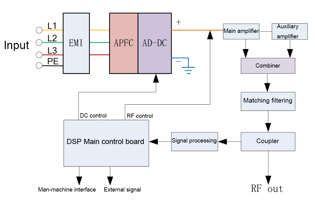
System chart

APFC: Incoming line Power Factor Correction
AC / DC: Power amplifier power supply, adjust the output voltage to change the output power
Main control board: signal processing, function control and RF amplifier control
Amplifier: Switching type amplifier, including signal source (crystal generated), drive and amplification
Combiner: Combiner of output power signals
Matching filtering: main reactance transformation, output 50 ohms
Coupler: forward and reverse power detection
Features of RF power supply:
1. AC 220V and 380V input voltage optional;
2. The incoming line has an APFC module to improve the input side power factor;
3. The frequency conversion series has the function of automatic load matching, which can work and switch under fixed frequency and frequency conversion;
4. With advanced software algorithms, such as: heuristic intelligent frequency tracking, intelligent power limit algorithm, etc .;
5. Using NXP power amplifier chip, high precision 16-bit synchronous ADC;
6. Full digital control, high stability and rich operation menu;
7. RS232, EtherCAT, EtherNET communication interface;
13.56MHz Main Specifications
Input indicators | ||
1 | AC input voltage | 220VAC±10% or 380V±5% |
2 | AC input frequency | 50Hz/60Hz |
3 | Ground leakage current | <4mA |
4 | Power factor | 0.98, full power output, standard load: 50Ω |
5 | Efficiency | >75%, Z = 50Ω, FWD = rated power |
Output indicators | ||
1 | Output frequency | 13.56MHz |
2 | Frequency stability | ±0.005% (25℃) |
3 | Load impedance | 50Ω-j0 |
4 | Output power adjustment | FWD forward power |
5 | Maximum output power | 5000W (Load:50Ω) |
6 | Output power range | 1~100%, 30W~5000W |
7 | Reverse power limit | MAX: 15% rated power (settable by software) |
8 | Output dynamic response | Less than 200mS |
9 | Output power accuracy | FWD<300W, < ± 3W FWD>300W, < ± 1% of setting power Load: 50Ω |
10 | Output power repeatability | ±1%, greater than 5% of set power |
11 | Output power stability | <±1% Load:50Ω |
12 | Output power leakage | < 1W, RF-ON, set power = 0W < 0.5W, RF-OFF |
13 | Pulse frequency | 100Hz~10KHz |
14 | Pulse duty cycle | 10% ~ 90%, 1% step length |
15 | harmonic | <-45dB, FWD>300W |
16 | Stray | <-55dB, FWD>300W |
Control and display | |||
1 | remote control | Analog / digital interface (D-sub 25 pin female) RS232 communication (D-sub 9-pin male) | |
2 | Set minimum power step length | Communication or digital setting: 1W; analog setting:3W | |
3 | display | Set power | 0~5000W |
Forward power | 5000.0W | ||
Reverse power | 800W | ||
frequency | 0.0000MHz | ||
Power status | 1.Stop 2.Standby 3.Run | ||
Fault alarm | Memory failure, overheating, DC overcurrent, internal lockout, fan failure, reverse power overrun, external lockout, overrun overrun, tuning overrun | ||
4 | Ramp (type optional) | Time: 0.1 ~ 3000.0S | |
Slope: 0.1 ~ 1000.0W / S | |||
Close | |||
Physical parameter | ||
1 | Size | |
2 | RF output interface | N-type or 7/16 |
3 | AC input interface | MS-3102A-22-22P (4-pin aerial plug male) |
4 | User Control Interface | D-Sub 25 pin female |
5 | Communication Interface | D-Sub 9 pin male |
6 | Cooling water connection | PT 3/8 (female) |
7 | Grounding stake | M5 |
Use environment | ||
1 | Ambient temperature | 5 ~ 40℃ |
2 | environment humidity | 15 ~ 85% |
3 | Cooling water temperature | 20 ~ 30℃ |
4 | Cooling water pressure | 0.3 ~ 0.5MPa |
5 | Cooling water quality | Pure water or deionized water |
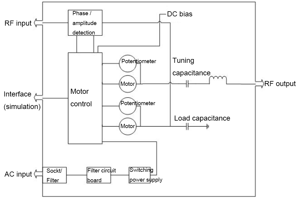
RF Matcher Block Diagram

RF matcher description
RF input and RF output: The RF power source inputs power into the matcher network, and the power is adjusted by the matcher and then connected to the load.
Load capacitance and tuning capacitance: The matching network structure adopts L-type topology, and the load capacitor and tuning capacitor are variable capacitors.
AC input: matching network control power supply.
Phase / amplitude detection: The RF power is connected to the matching network through the RF generator on the phase / amplitude sensor module. The phase / amplitude module provides phase and amplitude signals to the motor control section, thereby controlling the rotation of the load capacitor and tuning capacitor.
Motor control: The phase and amplitude signals are used to generate the driving signals required by the motor for adjustment. Manual control and automatic control can be set. Adjust the position value and limit value of the capacitance through the voltage provided by the potentiometer. After the motor reaches the mechanical limit value, it needs to rotate in the reverse direction.
DC bias: The DC bias voltage is provided by the PCB board and the motor drive control board. The DC bias board provides voltage divider. motor drive board rectifies dc offset voltage, so that the make the interface DC bias voltage always positive.
Matcher main technical indicators
Input indicators | ||
1 | AC input voltage | 220V ± 10% |
2 | AC input frequency | 50Hz / 60Hz |
3 | AC input current | 0.5 ~ 1A |
4 | RF input interface | N-type RF coaxial connector |
5 | RF input impedance | 50Ω |
Output indicators | ||
1 | Output frequency | 13.56MHz |
2 | Output Interface | Copper bar or 7/16 connector |
3 | RF maximum output voltage | 4000Vpp |
4 | Load matching range | R (5 ~ 200) + j (+ 200 ~ -200) Ω |
5 | Maximum output power | 5000W (Load: 50Ω) |
6 | Reflected power | 5W or 1% of forward power |
7 | Tuning time | End-to-end <5S, preset point to match point <0.5-3S |
8 | Standing wave | Standing wave after matching <1.2 |
9 | Adjustment method | Manual / automatic free switching |
Use environment | ||
1 | Ambient temperature | 5 ~ 45℃ |
2 | environment humidity | 15 ~ 85% |
3 | Cooling water temperature | 20 ~ 30 ° C |
4 | Cooling water pressure | 0.3 ~ 0.5MPa |
5 | Cooling water quality | Pure water or deionized water |
Copyright © Zhengzhou CY Scientific Instrument Co., Ltd. All Rights Reserved Update cookies preferences
| Sitemap | Technical Support: 